 English
 Español
 عربى
عربى1. Space Efficiency: How Does an Expandable Container House Maximize Living Area? Expandable container houses are a re...
READ MOREHow Electrical Plans and Symbols Define Safe Wiring in Container Structures
Update:30 Jul 2026
Why Electrical Plans Matter in Modular Container Construction
Modular container buildings now serve as site offices, guard posts, dormitories, pop-up retail units, and temporary clinics. Unlike timber-framed houses, these structures use a steel shell that changes how cables, boxes, and fixtures are routed. A proper residential electrical plan translates the intended position of every socket, switch, and light fixture into a document that installers can follow before the wall panels are sealed and the unit is shipped to site.
For a typical mid-size container office, planners commonly allow for six to ten duplex receptacles and two to four lighting circuits, depending on room count and appliance load. Skipping this planning step is the most frequent cause of rework, since drilling through a finished steel or sandwich panel wall after assembly is far more disruptive than marking positions on a plan first.
Two structural variations matter most in this niche: the corrugated container house, built from ribbed steel sheeting, and the folding container house, which uses hinged modules that collapse for transport. Each requires the electrical plan to account for a different wall profile and a different assembly sequence, which later sections cover in detail.
A clear electrical plan reduces on-site labor time by allowing conduit and box positions to be pre-marked on panels during factory fabrication rather than measured again after delivery.
Standard Electrical Plan Symbols Reference
Every electrical plan symbols set follows a broadly consistent visual language, even though drafting styles vary between regions. Recognizing these marks lets a site team, a client, and an installer read the same drawing without confusion. The table below lists the marks most often found on a container house layout.
| Symbol Name | Typical Mark | Function on the Plan |
|---|---|---|
| Duplex outlet symbol | Circle with two short parallel lines | Marks a standard two-receptacle wall socket |
| Single-pole switch symbol | Circle with letter S | Controls one lighting circuit from a single location |
| Three-way switch symbol | Circle with S3 | Controls one fixture from two separate switch points |
| Weatherproof outlet symbol | Circle with WP | Marks an exterior or wet-area receptacle |
| Ceiling light symbol | Circle with cross lines | Marks a ceiling-mounted fixture location |
| Junction box symbol | Small square | Marks a cable splice or connection point |
| Panel board symbol | Rectangle with internal lines | Marks the distribution board feeding all circuits |
Consistency in these marks across a project matters more than the exact style chosen, since mismatched symbols between the plan and the as-built wiring are a common source of maintenance errors later.
Wall Outlet Symbol and Duplex Outlet Placement Rules
The wall outlet symbol and the symbol for an electrical outlet mean the same thing in most drawing sets: a circle placed against a wall line, usually offset slightly to show it sits on the vertical surface rather than the floor. On a container house plan, this symbol needs a note showing mounting height, since the steel wall build-up changes how deep the receptacle box can sit.
Common placement guidance for this housing type includes the following points.
- Mount general-purpose outlets 300 to 450 millimeters above finished floor level.
- Space wall outlets so no point along a usable wall run is more than roughly 3.6 meters from a receptacle.
- Place a dedicated duplex outlet symbol within one meter of any built-in desk or counter run.
- Use the weatherproof variant for any receptacle on an exterior wall or in a wash area.
- Keep outlet boxes at least 300 millimeters clear of door swing lines to avoid furniture conflicts.
Light Switch Symbols and Circuit Grouping Strategy
The light switch symbol is typically drawn at a consistent height mark of about 1.2 meters and positioned on the latch side of a doorway rather than the hinge side, so a person entering the room can reach it without crossing the space in the dark. On plans for folding or multi-module container units, three-way switching is worth specifying for any corridor or shared space that has two entry points, since a single switch location would otherwise force occupants to walk the length of the room to turn off a light.
Grouping circuits logically also keeps the electrical plan easier to read and the panel board easier to label later. A practical grouping pattern for a small container structure looks like this.
| Circuit | Typical Load | Symbols Included |
|---|---|---|
| Circuit 1 | General lighting | Ceiling light symbol, switch symbol |
| Circuit 2 | General receptacles | Duplex outlet symbol along interior walls |
| Circuit 3 | Kitchenette or wet area | Weatherproof outlet symbol, dedicated appliance outlet |
| Circuit 4 | HVAC or heater unit | Dedicated outlet symbol, isolator switch mark |
Adapting Electrical Plans to Corrugated Container House Panels
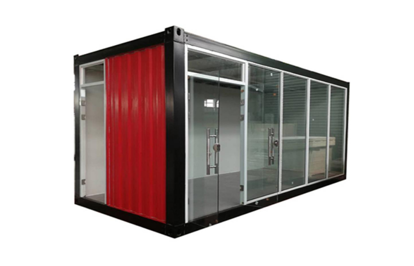
A corrugated container house uses ribbed steel sheeting for its wall skin, which changes two things on the electrical plan: cable routing and box mounting depth. Cables generally run inside the flat channel formed between the corrugation ribs and the interior lining board, and the plan should note this channel width so the installer selects boxes that fit without crushing the insulation layer.
Because the ribs create a repeating pattern, outlet and switch symbols are easiest to place at the flat sections between ribs rather than mid-rib, which keeps the receptacle face flush with the finished interior surface. The steel frame itself also needs a bonding conductor noted on the plan, since the structural skin functions as a large conductive surface that should be tied to the grounding system rather than left floating.
Typical adjustments for this wall type include allowing extra depth for the outlet box where the corrugation trough is shallow, marking cable entry points at panel joints rather than through solid rib sections, and specifying corrosion-resistant fasteners for any exterior-facing fixture bracket.
Wiring Layouts for Folding Container Houses at Fold Lines
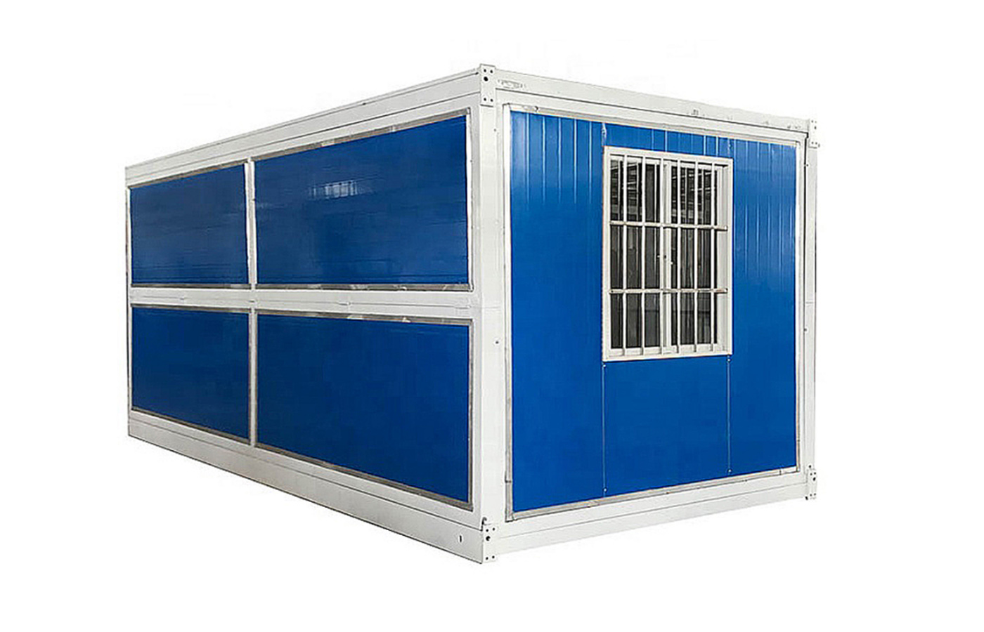
A folding container house introduces a wiring constraint that a fixed-shell unit does not have: the structure physically folds flat for transport, which means any cable crossing a hinge line must either disconnect cleanly before folding or use a flexible loop with enough slack to absorb the movement.
The electrical plan for this structure type should mark disconnect points explicitly, usually with a quick-connect junction symbol placed just to either side of each hinge line, rather than running a continuous cable across the fold. Junction boxes near these points are typically mounted slightly recessed so the folding panel edge does not catch on the box housing during collapse.
Grounding continuity across the fold also needs a note on the plan, since bonding straps must be reconnected each time the unit is deployed, and this step is easy to overlook if the drawing does not flag it clearly.
Common Electrical Plan Mistakes to Avoid
Several recurring errors show up on container house electrical drawings, and most are avoidable with a short review pass before fabrication begins.
- Skipping a basic load calculation before deciding circuit count, which leads to overloaded breakers once appliances are added.
- Leaving the steel frame ungrounded because the bonding note was left off the plan.
- Placing outlet symbols without a circuit number, which makes later panel labeling guesswork.
- Using a standard outlet symbol on an exterior wall instead of the weatherproof variant.
- Running a continuous cable across a fold line on a folding container house without a disconnect point.
- Omitting a dedicated circuit for HVAC or water heating equipment, which are typically higher draw loads.
Frequently Asked Questions
Q1: What is the difference between a wall outlet symbol and a duplex outlet symbol?
A wall outlet symbol is the general mark for any receptacle on a wall, while a duplex outlet symbol specifically indicates a socket with two receptacle points, shown by the two parallel lines inside the circle.
Q2: Why does the electrical plan matter more for container houses than for standard homes?
The steel shell and, in some cases, a folding structure limit where cables and boxes can be routed, so positions need to be confirmed before panels are closed rather than adjusted afterward.
Q3: How high should switches and outlets be placed on the plan?
A common reference is roughly 1.2 meters for switches and 300 to 450 millimeters for general outlets, though exact heights should follow the applicable local code for the project location.
Q4: Do corrugated container houses need special outlet boxes?
Outlet boxes for corrugated panels are typically placed at the flat sections between ribs and may need adjusted depth to sit flush with the interior lining, depending on the panel profile.
Q5: What should the plan show at a folding container house hinge line?
The plan should mark a quick-connect or disconnect point on each side of the fold line rather than a continuous cable, along with a note on reconnecting the grounding strap after each deployment.
Q6: Can one electrical plan be reused across multiple container house sizes?
A base layout can be adapted, but outlet spacing, circuit count, and switch positions usually need rechecking against the specific room dimensions and load requirements of each unit.
News
GET A QUOTE
Contact Us Now

We can do OEM and ODM to meet all your detailed requirements. Allstar will be your choice. You are warmly welcome to visit and consult!
Our Product
Quick Links
Contact Information
- Add: No.218, Calle Xinlou, Pueblo de Qutang, Ciudad de Haian, Provincia de Jiangsu, China.
- E-mail: [email protected]
- Phone: +86-21-67353838
+86-513-88798719
Copyright © 2025 Shanghai Allstar Industrial Co., Ltd. All Rights Reserved.
Customized One-Stop Service Container House Suppliers
 Privacy
Privacy
