 English
 Español
 عربى
عربى1. Space Efficiency: How Does an Expandable Container House Maximize Living Area? Expandable container houses are a re...
READ MOREWhy Expandable and Modular Container Houses Form the Future of Global Infrastructure
Update:02 Jul 2026
The Structural Paradigm Shift in Modern Architecture
Urbanization, environmental challenges, and shifts in workforce mobility have transformed the requirements of contemporary real estate. Traditional concrete and brick infrastructure, while historically reliable, faces criticism for its lengthy construction timelines, high labor costs, and substantial carbon footprint. In response, engineering frameworks have evolved to embrace modular construction, shifting fabrication from unpredictable outdoor environments into high-precision factories.
This industrial evolution has positioned industrialized structures as sustainable alternatives rather than temporary alternatives. Among these innovations, a clear progression exists from standard maritime intermodal containers to specialized architectural solutions. Understanding how these modular systems diverge from historical transport containers requires a close analysis of structural profiles, load bearing properties, and spatial maximization capabilities.
70%
Reduction in Total Project Construction Timelines Compared to Traditional On-Site Construction Methods
Zero
Wet Structural Waste Generated On-Site During the Installation and Assembly Phase
100%
Structural Reusability and Relocation Capability Over a 25-Year Operational Lifespan
Distinguishing Cargo Units from Engineered Habitats
The conceptual origin of modern modular dwellings traces back to standard shipping container houses. Traditional logistics containers are manufactured using structural Cor-Ten steel sheets corrugated horizontally to maximize structural stiffness against lateral ocean forces. While highly rigid, converting a raw cargo shell into a habitable unit presents major engineering challenges. Standard units measure 8 feet in width, which shrinks further once structural thermal insulation barriers, internal wall panels, and utility raceways are installed inside.
Modern industrial modular architecture resolves these dimensional limits by decoupling structural strength from static external walls. Instead of modifying rigid cargo boxes, advanced engineering utilizes custom structural hollow section frameworks made from hot-dip galvanized steel. This evolution allows for variable geometric form factors, optimized thermal insulation spacing, and specialized mechanical hinges. These modern systems fall into distinct structural families, each designed to meet specific transport and operational goals:
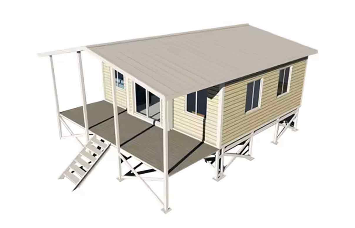
- Dynamic Mechanized Volumes: Typified by the engineered expandable container house, these systems utilize articulated telescoping nested frames to multiply spatial footprints when deployed on site.
- Aerodynamic Monocoque Enclosures: Categorized as a apple cabin container house or a luxury capsule house, these units focus on organic, high-performance exterior shells, curved structural glazing, and pre-integrated digital control networks.
- High-Density Logistics Profiles: Utilizing folding modular home mechanisms, these solutions collapse down to a fraction of their functional height, minimizing transport overhead across long supply chains.
The Mechanics of Folding Modular Homes
While expandable configurations emphasize maximizing volume on site, a folding container house focuses on shipping efficiency and rapid on-site assembly. These structures are engineered to optimize international shipping costs by maximizing the number of structural modules that can fit into standard transport configurations.
Logistical Efficiency and Volumetric Dynamics
Standard transport methods often incur high costs when shipping fully assembled modular homes due to empty space charges. A folding modular home addresses this issue by reducing its vertical profile when collapsed. The structural joints use heavy-duty industrial scissor hinges and dual-pin pivot arrangements, allowing all four exterior walls to fold flat onto the integrated chassis frame.
| Engineering Parameter | Standard Operational Mode | Stowed Shipping Configuration |
|---|---|---|
| Vertical Clearance Height | 2580 mm | 390 mm |
| Volumetric Transport Density | 1 Unit per Trailer Flatbed | 6 to 8 Units per Standard Flatbed |
| Deployment Duration Matrix | 4 Structural Riggers / 12 Minutes | Not Applicable |
| Interlocking Corner Casting Class | ISO 1161 Standard Structural Corner Block | ISO 1161 Standard Structural Corner Block |
Structural Stability Under Variable Dynamic Loads
A primary engineering concern for foldable vertical structures is ensuring long-term resistance to lateral wind stress and seismic loads. When a folding structure is fully extended, its joints must lock securely to prevent mechanical play. This stability is achieved by using high-tensile interlocking pins that pass through CNC-machined alignment tabs placed at every structural hinge point.
Once the building is erected, the structural framework transforms from a series of moving parts into a stable three-dimensional box truss system. The vertical wall panels transfer dead loads downward into the primary structural floor beams, while structural interlocking keys at the upper ceiling frame prevent buckling from uniform snow loads. This design allows foldable structures to withstand continuous wind speeds up to 110 kilometers per hour without needing permanent auxiliary internal columns.
The Technical Evolution of the Apple Cabin Container House
In contrast to the industrial angularity of expandable or foldable units, the apple cabin container house introduces a distinct architectural approach. These modern prefab cabins use curvilinear monocoque design principles, focusing on aerodynamic aesthetics, advanced composite materials, and seamless structural integration for luxury glamping pods and futuristic tiny houses.
Monocoque Construction and Advanced Composite Shells
The main structural feature of an Apple Cabin is its continuous, curved exterior skin. This design moves away from flat panel welding, utilizing multi-layered fiber-reinforced polymer (FRP) composites or high-grade formed aluminum alloy panel systems instead. Drawing from aerospace manufacturing techniques, the exterior shell reduces structural seams, significantly lowering the risk of water ingress over time.
The curved framing layout distributes external physical loads evenly across the entire surface of the building. Inside, the core frame uses specialized bent structural tubing to support large panoramic glass elements. This configuration allows for wide, uninterrupted viewing angles, making these cabins well-suited for high-end eco-tourism and architectural hospitality installations.
Glazing Systems, Thermal Efficiency, and Smart Automation
The curved panoramic windows require advanced glass configurations to maintain structural safety and thermal efficiency. These cabins use double-glazed or triple-glazed argon-gas filled tempered glass units with integrated low-emissivity (Low-E) metallic coatings. This setup allows visible light to enter while reflecting infrared and ultraviolet radiation, preventing greenhouse-style overheating in warmer months.
These structures are also pre-configured for automated climate and utility control. Internal building management networks link automated environmental sensors directly to variable-refrigerant-flow (VRF) climate control units. Digital access controls, motorized black-out window systems, and integrated greywater filtration units allow these modern cabins to function efficiently either as standalone grid-connected dwellings or within remote off-grid locations.
Comparative Architectural Matrix
Selecting the appropriate modular architecture depends on balancing specific technical tradeoffs, including cost structures, wind resistance capabilities, transport efficiency, and site preparation requirements. The table below outlines these engineering metrics to assist in technical decision-making.
| Architectural Category | Primary Structural Framework | Wind Resistance Capacity | Thermal Transmittance (U-Value) | Optimal Deployment Use Case |
|---|---|---|---|---|
| Expandable Container House | Articulated Galvanized Box Section Truss | Zone 2 (Up to 105 km/h) | 0.32 W/m²K (With PU Core Insulation) | Semi-Permanent Suburban Housing / Multi-Room Family Dwellings |
| Folding Modular Unit | Linked Mechanical Scissor Hinge Frame | Zone 1 (Up to 90 km/h) | 0.40 W/m²K (With EPS Core Panels) | Rapid Disaster Relief / Temporary Worksite Camps / Bulk Logistics |
| Apple Cabin Enclosure | Curvilinear Monocoque Frame Skeleton | Zone 3 (Up to 125 km/h) | 0.28 W/m²K (With Composite Layers) | Luxury Glamping / Remote Eco-Resorts / High-End Studio Offices |
Site Infrastructure and Engineering Integration
Although modular buildings are fabricated in factory environments, long-term durability depends on proper site preparation and precise infrastructure integration. Without correct foundation engineering, soil shifts can misalign mechanical joints, causing issues with windows, doors, and folding sub-frames.
Precision engineering site layout showing localized concrete pier foundations coupled with underground mechanical, electrical, and plumbing utility hookups.
Foundation Design and Ground Anchor Subsystems
Modular buildings require tailored foundation engineering based on local soil conditions and planned usage duration. Helical screw steel piles are commonly used for temporary installations or areas with sensitive ecosystems. These piles are driven deep into stable soil layers, providing strong uplift resistance against high winds while minimizing surface ground disruption.
For permanent installations, a reinforced concrete pier foundation layout is preferred. Concrete piers are poured at precise structural node intersections, particularly beneath high-load hinges and expanding cantilever corners. The steel chassis of the module is then bolted directly to heavy steel plates embedded in the concrete using high-tensile anchor bolts. This elevates the bottom frame away from surface water and prevents moisture damage over time.
Mechanical, Electrical, and Plumbing Connection Formats
To maintain rapid assembly advantages, utility connections use pre-engineered quick-connect interfaces. The plumbing systems feature dedicated external connection points containing all intake and drainage lines:
- Freshwater Input: Integrated 3/4-inch brass pressure fittings designed for quick coupling to municipal water networks or high-pressure pump setups.
- Blackwater Output: Heavy-walled 4-inch PVC drainage valves utilizing quick-twist bayonet mountings matching standard waste systems.
- Electrical Supply: Industrial grade external waterproof shore-power inlets (32A/63A single or three-phase) feeding directly into an internal circuit breaker panel.
Frequently Asked Technical Questions
Q1: How do mechanical expansion joints maintain reliable water sealing over years of operation?
The long-term weather tightness of expandable structures relies on multi-layered compression seals made from high-grade EPDM rubber compounds. When the side wings open fully, structural toggle clamps compress these gaskets by up to 30 percent, creating a watertight barrier against driving rain. Additionally, the exterior metal frame features integrated overlapping drainage channels that direct water away from the joint faces, utilizing gravity to prevent water pooling near structural seams.
Q2: Can these modular buildings operate in extreme winter environments without interior freezing?
Yes, these units can operate effectively in sub-zero climates when configured with high-density polyurethane or structural rock wool insulation layers. Minimizing thermal bridging requires placing non-conductive isolation spacers between the internal wall panels and the main steel chassis. When paired with double-glazed Low-E windows and properly sized heat pump systems, these structures easily maintain stable interior temperatures even when outside conditions drop below minus twenty degrees Celsius.
Q3: What foundation tolerances are required to ensure proper deployment of folding modules?
Folding and expanding structures require precise leveling across the foundation site. The horizontal alignment variance between foundation piers should not exceed plus or minus 5 millimeters across the full length of the building chassis. If the site exceeds this tolerance, the structural hinges can experience binding forces, which increases mechanical wear during deployment and may cause minor gaps in the primary perimeter seals.
Q4: How do composite shells perform under high solar radiation and extreme heat?
The curved composite shells used in modern cabins are finished with marine-grade, ultraviolet-stabilized gel coats or fluoropolymer coatings. These specialized outer layers reflect a significant portion of solar radiation and resist chalking, fading, and micro-cracking over long exposure periods. This material stability ensures the building retains its structural strength and appearance throughout its operational life.
News
GET A QUOTE
Contact Us Now
We can do OEM and ODM to meet all your detailed requirements. Allstar will be your choice. You are warmly welcome to visit and consult!
Our Product
Quick Links
Contact Information
- Add: No.218, Calle Xinlou, Pueblo de Qutang, Ciudad de Haian, Provincia de Jiangsu, China.
- E-mail: [email protected]
- Phone: +86-21-67353838
+86-513-88798719
Copyright © 2025 Shanghai Allstar Industrial Co., Ltd. All Rights Reserved.
Customized One-Stop Service Container House Suppliers
 Privacy
Privacy
